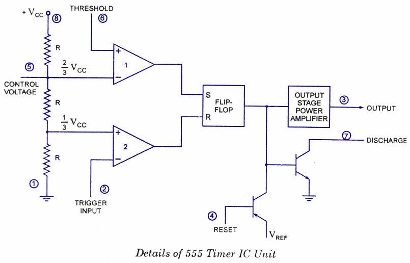
Timer 555 Internal Structure
555 timer diagram circuits electronic Introduction to the 555 timer 555 timer internal diagram pinout function ic circuit working construction application electricaltechnology schematic functional block voltage output operation its types
voltage - What would be the output of a 555 multivibrator ic in
555 timer ic 555 timer working electrical4u diagram internal block 555 timer electrosome
555 timer ic circuits ne555 monostable internal multivibrator ics bistable
Cmos 555 timer: structure explained and reverse engineered « adafruit555 timer ic diagram block working functional principle internal circuit schematic comparator avr pic ready help Timer pinout modes من الجهد555 timer ic internal diagram structure comparator trigger two flip flop schmitt voltage inside components look figure circuits positive example.
How does a 555 timer work?Engineering and information: what is 555 timer..how its working? 555 timer diagram chip ic block circuit transistor electronics discharge do output does logic reset tutorial multivibrator gif flop flipTimer 555 diagram circuit schematic ne555 pinout datasheet block does circuits flop flip works discrete kit eleccircuit integrated output connection.

Explain the functional block diagram of timer ic555
Panic alarm circuit diagram using 555 timer ic555 timer diagram internal ic astable circuit multivibrator monostable bistable Timer diagram functional ic block 555 ic555 flop flip figure555 timer ic pin diagram features and applications.
555 timer ic555 timer ic 555 timer and 555 timer working555 timer ic.

How does ne555 timer circuit work
555 timer cmos diagram chip reverse oscillator structure explained engineering operation timing engineered operate showing ic adafruit die explanation engineersTimer block pinout modes من الجهد 555 timer electronics lambert555 timer ic: internal structure, working, pin diagram and description.
Ready to help: functional block diagram of ic 555Timer 555 ic alarm panic dip internal generator circuit lm555 kicad using structure entegresi pulse designing pcb button ezcontents electronic .


555 Timer IC - Features, Pinout, Working, Circuit, Operating Modes

555 Timer IC

How Does a 555 Timer Work? - Cloud Information and Distribution

voltage - What would be the output of a 555 multivibrator ic in

555 Timer and 555 Timer Working | Electrical4u

555 Timer IC Pin Diagram Features And Applications | 555 Timer working

555 Timer IC: Internal Structure, Working, Pin Diagram and Description

Ready to help: Functional Block Diagram of IC 555

CMOS 555 Timer: Structure Explained and Reverse Engineered « Adafruit
