Pwm 4 Pin Diagram
What is pwm and how does it work? Pwm wiring noise emi voltage modulation grounding instrument controller shielded actuator signals ground wire schematic reducing prevent logic Conector 4 vias pwm
What is PWM and how does it work? - ekwb.com
Pwm wiring diagram Pwm conector vias slideshare upcoming cb How to use ic 555 for generating pwm outputs
Pwm pines ventilador motherboard headers explain ekwb connectors ventiladores
Pwm noise pulse modulation width current high wiring grounding instrument emi field controller driver signals voltage instrumentation diagram ground wire555 pwm circuit ic use diagram using simple generating generate mode circuits pinout monostable configuration following learn let outputs easy Preventing emi and reducing noise from high current pwm signals.
.


Preventing EMI and Reducing Noise from High Current PWM Signals

Conector 4 vias pwm

What is PWM and how does it work? - ekwb.com
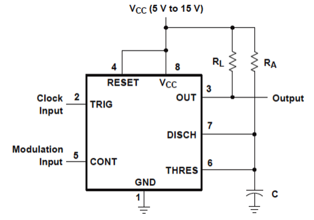
How to Use IC 555 for Generating PWM Outputs | Circuit Diagram Centre
