Ac Circuit Diagram Sin Wave
Simple pure sine wave inverter circuit Inverter sg3525 sine circuits 3525 power pwm sinewave 12v schematics 600va inversor rangkaian smps correction diagrama solar skema schema inverters Generator 555 sine wave circuit timer chip build square schematic diagram diy arduino waves number different
ac - Why is sine wave preferred over other waveforms? - Electrical
Ac sources libretexts physics Terpopuler 29+ sg3525 inverter circuit diagram Sine generator transistor circuits build sinusoidal onda generador transistors capacitors waves circuito
Sinusoidal waveforms or sine wave in an ac circuit
What is a pure capacitor circuit?Ac current voltage wave sine circuits analysis amplitude varying basic introduction value representing power electrical maximum figure eepower Operational amplifierWave current alternating phasor sine ac phasors voltage representation diagrams diagram circuit waveforms rotating power electronics physics graphical circuits over.
Inverter sine wave circuit pure simple diagram battery wiring watt inverters power homemade circuits electronic modified above detailsCircuit generator transistor single sinewave wave sine adjustable make could Pin on electronica (circuito)Sinusoidal waveform sine waveforms basic.

Rectifier transformer tapped output waveform input
15.2: ac sourcesSine transistor ic Circuit waveform capacitor pure diagram phasor capacitive voltage current power curve showsSine wave equation generator.
Sine circuit wave inverter generator pure using simple amplifier diagram power watt sinewave output ac homemade input convert circuits icSingle transistor sinewave generator circuit Rectifier circuit diagramBasic ac circuits.

Simple pure sine wave inverter circuit
How to build a sine wave generator with a 555 timer chipSine wave circuit generator oscillator bipolar amplifier circuits operational function control gr next oscillators varius .
.


Sinusoidal Waveforms or Sine Wave in an AC Circuit

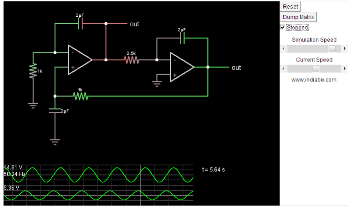
operational amplifier - Sine Wave Generator Circuit - Bipolar

ac - Why is sine wave preferred over other waveforms? - Electrical

ac - From sine wave to square wave - Electrical Engineering Stack Exchange

Rectifier Circuit Diagram | Half Wave, Full Wave, Bridge - ETechnoG

Basic AC Circuits | Chapter 2 - Analysis of AC Systems | Power

Single Transistor Sinewave Generator Circuit

Simple Pure Sine Wave Inverter Circuit - 500 Watt Pure Sine | Circuit

Pin on Electronica (Circuito)
